You have no items in your shopping cart.

WEG CWBS Safety Contactors
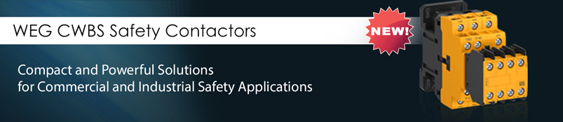
INCREASED SAFETY FOR OPERATORS AND EQUIPMENT
WEG's new CWBS line of contactors for safety applications was developed in compliance with IEC and UL standards. These contactors feature mechanically linked contacts (IEC/EN 60947-5-1) and mirror contacts (IEC/EN 60947-4-1) which provide proper operation of safety circuits for machines and equipment that must operate in compliance with international safety standards.
Main Characteristics
|
|
Benefits
|
|

Construction Features

Mechanically Linked Contacts
(IEC/EN 60947-5-1 - Annex L) 
This standard is applicable to the auxiliary contacts used in auxiliary control circuits. Those contacts can be built into the contactor or blocks of external auxiliary contacts mounted on the contactors. According to IEC/EN 60947-5-1 - Annex L, open contacts and closed contacts cannot be simultaneously closed. In case welding occurs on the NO contacts, the NC contacts must remain open, and in case welding occurs on the NC contacts, the NO auxiliary contacts must remain open. The following example shows that characteristic:
|
|
Some other names may also be given to this same requirement of the standard in technical documents, such as: forced contacts, positively activated contacts, linked contacts and positively guided contacts. Contactors with that characteristic are often used in self-monitoring circuits combined with safety interfaces (e.g., safety relays) used in the automation and safety of machinery and equipment. Contactors which do not meet that requirement may damage the equipment or harm the operator.
|


Mirror Contact
(IEC/EN 60947-4-1 - Annex F) 
This standard is applicable to the auxiliary contacts mechanically linked to the power contacts. When the contactor coil is energized, the power contacts will be closed and at the same time the NC auxiliary contacts will be open. Those auxiliary contacts are called mirror contacts.
All article contributions and figures courtesy of WEG.
For more information about WEG products or switchgear, get in touch with our experienced technicians.
Local (07) 55 353217 | AUS 1800 633 040 | NZ 0800 633 040
December 2025. This publication may contain references to products produced and/or offered by other companies. The product and company names may be trademarked and are the sole property of their respective owners. Direct Automation Pty Ltd disclaims any proprietary interest in the marks and names of others. All prices shown are trade prices and are exclusive of GST. Prices are subject to change, orders will be accepted at the pricing ruling at the time of our acceptance of orders. Please refer to our online store for current prices. Images for display purposes only and may be generic.